Shift Box
DSM BASIC2 -
Product Support Page
Last updated 9/26/15
Basic instructions:
-
Once installed, this shift box is simple to use. Simply
press the up-shift button to advance to the next gear, or
press the down-shift button to drop to a lower gear.
-
This shift box will boot up in 3rd gear every time as a
safety in case the shift box would ever reboot due to a
power connection problem.
-
By default the downshift protection RPM is 4500RPM, see the
menu below to change this, or disable the downshift
protection.
-
To use the RPM up-shift feature, you must set the shift
points to your desired RPM in the menu. Set the shift point
~1000RPM sooner than you want the shift to be made to start,
and adjust as necessary. This is due to the delay inside the
transmission to engage the clutches. You must enable the
UP-SHIFTER in the menu to begin using this feature.
-
The overdrive off feature can be used by up-shifting to 4th
gear. Press and hold the up button until the O/D off LED
illuminates and the shift box downshifts to 3rd gear. To
turn O/D back on, up-shift to 3rd gear and press and hold
the up button until the O/D off LED turns off and the shift
box up-shifts to 4th gear.
-
The torque converter lock-up feature, when enabled, will
illuminate the green LED when the solenoid is turned on
-
Note that the shifts are made at full line pressure, so
learning the timing on when to make the shift will make
using this shift box much more pleasurable on the street.
Using the menu:
·
To
enter the menu:
o
Downshift to 1st gear then press and hold down shift button
until menu opens
·
Basic tips for easier navigation:
o
Default values are shown as underlined
o
Bold
text is word for word what the shift box will display
o
You can skip to the next menu option without waiting for
the text to be displayed
o
Wide open throttle will toggle some values the opposite
direction (requires TPS wire connected)
o
Up
button selects or toggles a item/value, down button
advances to the next menu item
o
Menu will automatically save settings and exit
after a few seconds of user inactivity
MENU
BRIGHTNESS = 5
(Default is 5, 1=dimmest, 5=brightest)
GLOW-BUTTONS = ENABLED/DISABLED (Default is
enabled if glow button feature is available)
RPM-UP-SHIFTER = ENABLED/DISABLED
(Default is disabled, enable to use the auto up-shift feature)
TRAILING-ZEROS = ENABLED/DISABLED (Default is
disabled, shows 5000RPM as 50 & 750ms as 75 for faster menu
displaying)
DOWN-SHIFT-PROTECTION = ENABLED/DISABLED (Default
is enabled, change if you do not wish to use the down-shift
protection)
GEAR-SCROLL = ENABLED/DISABLED (Default is
enabled. This option changes whether the gear numbers scroll or
simply change)
LOCK-UP = ENABLED/DISABLED (Default is disabled.
This option changes whether the lockup clutch feature is used,
when supported)
AUDIO = ENABLED/DISABLED (Default is enabled. This
option mutes the alerts when a shift is blocked, will not affect
the menu beeps)
DOWN-SHIFT-PROTECTION = 4500 (Configurable from
3500-7000RPM. Default is 4500RPM)
1-2-UP-SHIFT-RPM = 5500 (Set the 1-2 shift point,
configurable from 5000-12000RPM)
2-3-UP-SHIFT-RPM = 6500 (Set the 2-3 shift point,
configurable from 5000-12000RPM)
3-4-UP-SHIFT-RPM = 6500 (Set the 3-4 shift point,
configurable from 5000-12000RPM)
DEBOUNCE-UPSHIFT = 500 (Delay after auto up-shifts
to prevent double shifts, configurable from 500-1500 in 50ms
steps, 500=default)
LOCK-UP-FIRST = 00 (Default is OFF (00), Configure
minimum lock-up RPM or disable 1800-5500RPM)
LOCK-UP-SECOND = 3000 (Default is 3000RPM, Configure
minimum lock-up RPM or disable 1800-5500RPM)
LOCK-UP-THIRD = 3000 (Default is 3000RPM, Configure
minimum lock-up RPM or disable 1800-5500RPM)
LOCK-UP-FOURTH = 3000 (Default is 3000RPM, Configure
minimum lock-up RPM or disable 1800-5500RPM)
PULSE PER REV = 2 (Set the number of pulse per engine
revolution - 4 cylinder=2, 6 cylinder=3, 8 cylinder=4,
default=2)
RESTORE DEFAULTS? (Up button to restore factory default
configuration)
CONFIRM RESTORE DEFAULTS? (Up button to
confirm the restore defaults)
DISPLAY RPM (Up button displays current engine RPM,
useful for verifying proper installation)
ABOUT? (Up button displays current software version and
product web site address)
SAVE AND EXIT? (Up button to save and exit, down will
advance back to the first menu option)
*
All settings are saved to flash memory as soon as the menu is
exited, automatically
Updating the firmware / warranty:
-
The most recent DSM Shift Box BASIC2 firmware version is 001
-
Do not remove the serial number sticker from the back of the
shift box as this will be needed for any warranty claims
-
Please send an e-mail to
sales@forcedfour.com
to inquire about updating your firmware or to make a
warranty claim
-
(Note: All settings will be set to factory defaults when the
firmware is updated)
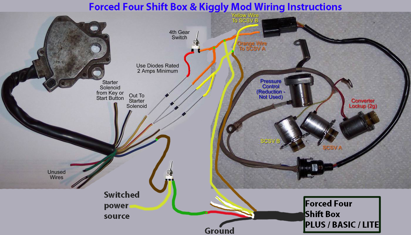
Wiring
instructions:
-
IMPORTANT NOTE:
If used with a TCU or other method of controlling the
transmission, follow the instructions closely. Only one way
of controlling the transmission should be powered on at one
time to prevent unexpected control of the transmission or
damage to the TCU. Use the supplied switch to switch between
transmission controls or substitute a suitable relay.
-
Use of diodes,
provided with the TCU package, is necessary to prevent
damage to TCU.
-
If the
transmission shifts from 1st to 4th to 3rd to 2nd, then the
shift solenoid wires are reversed
Using the DSM Shift Box BASIC2 as a standalone transmission
controller:
Bold print is required for normal operation, others depend on
usage and vehicle options
-
Red wire is +12
volt power from the ignition switch
-
Black wire is
ground, connect to a good clean chassis ground
-
White wire
splices with the crank sensor signal or tachometer signal
-
Yellow wire goes
to the Shift Solenoid A
-
Brown wire goes
to the Shift Solenoid B
-
Orange wire goes
to Converter Lock-Up Solenoid
-
Green wire is
the TPS signal, attach near ECU or TCU
-
White/Green wire
is the brake switch signal, attach to brake switch active
when +12V
-
Purple wire is
the up-shift button (short to ground to perform up-shift)
-
White/Purple
wire is the down-shift button (short ground to perform
down-shift)
-
Any remaining
wires should be capped
Using the DSM Shift Box BASIC2 with TCU or other transmission
controller:
Bold print is required for normal operation, others depend on
usage and vehicle options
-
Red wire is +12
volt power from the ignition switch, connect as follows
using switch harness
* NOTE:
On the fuse block there are 2 wires from the TCU fuse, both
must be cut and spliced together through the supplied switch
harness to prevent the TCU from being powered when the shift
box is being used.
Red wire (shift box) to Green wire (switch harness)
Yellow wire (switch harness) to fuse vehicle harness
(Power from TCU fuse)
Brown wire (switch harness) to fuse block harness (This
will power the TCU)
-
Red wire is +12
volt power from the ignition switch
-
Black wire is
ground, connect to a good clean chassis ground
-
White wire
splices with the crank sensor signal or tachometer signal
-
Yellow wire goes
to the Shift Solenoid A
(TCU must connect to solenoid through required diode)
-
Brown wire goes
to the Shift Solenoid B
(TCU must connect to solenoid through required diode)
-
Orange wire goes
to Converter Lock-Up Solenoid
(TCU must connect to solenoid through required diode)
-
Green wire is
the TPS signal, attach near ECU or TCU
-
White/Green wire
is the brake switch signal, attach to brake switch active
when +12V
-
Purple wire is
the up-shift button (short to ground to perform up-shift)
-
White/Purple
wire is the down-shift button (short ground to perform
down-shift)
-
Any remaining
wires should be capped
·
TCU
solenoid outputs connect to white/yellow side of diode included
with TCU package
Shift solenoid and shift box solenoid output connect to yellow
side of diode
Updating the firmware:
- The most recent Shift Box PLUS
firmware version is 001
- Please send an e-mail to
sales@forcedfour.com to inquire about updating your
firmware. Please note this shift box does not support
USB firmware updates and will need to be shipped to
Forced Four to be updated.
- (Note:
All settings will be set to factory defaults when
the firmware is updated)
Confused? Contact us at
sales@forcedfour.com
Installation
Instructions
Click to open
|