SMART 100.1 Shift
Box -
Product Support Page
Last updated 5/4/17
Forced Four SMART 100.1
INSTALLATION INSTRUCTIONS
-
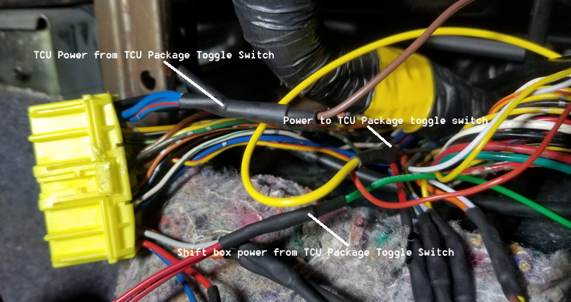
If used with a TCU or other method of controlling the
transmission, only one way of controlling the transmission
should be powered on at one time to prevent unexpected
control of the transmission or damage to the TCU. Use of our
TCU package or similar suitable switch/relay must be used to
power the TCU or shift box one at a time.
-
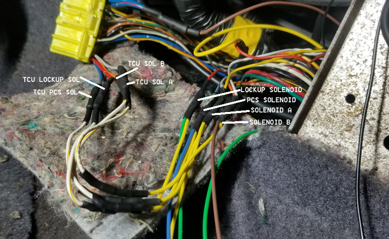
Use of diodes, provided with the TCU package, is necessary
to prevent damage to TCU.
-
The SMART 100.1 must be properly configured for your
transmission type before operating
-
Mount the SMART 100.1 unit in the vehicle cabin away from
heat and moisture, routing wires away from a CDI ignition
box or high voltage coil wiring recommended to prevent
erratic behavior.
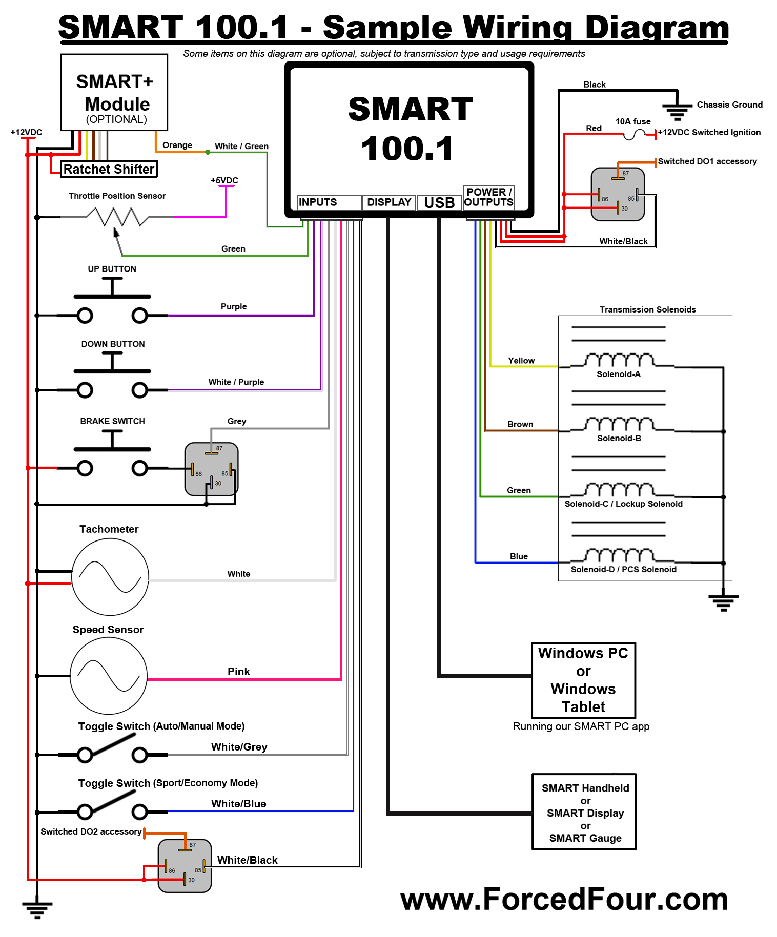
Wiring the SMART 100.1 shift box:
Any wires not used should be capped to prevent damage or
unwanted behavior!
USB
type mini connector
Display 8 pin
connector
Main 8 pin
connector [power, and outputs]
-
Yellow wire goes to Shift Solenoid A (SOL-A) (3A max)
-
White/Black wire is Digital Output #1 (DO1) switched to
ground when active (500mA max)
-
Brown wire goes to Shift Solenoid B (SOL-B) (3A max)
-
Black wire is ground, connect to a good clean chassis ground
-
Green wire goes to Shift Solenoid C OR Lockup Converter
(SOL-C) (3A max)
-
Red wire is +12 volt power from the ignition switch or TCU
fuse switched (18VDC max)
-
Blue wire goes to Shift Solenoid D OR Pressure Control
Solenoid (SOL-D) (8A max)
-
Red wire is +12 volt power from the ignition switch or TCU
fuse switched (18VDC max)
Main 10 pin
connector [Inputs]
-
Green wire is Analog Input #1 (AI1) typically TPS (0-5VDC)
-
White/Green wire is Analog Input #2 (AI2) (0-5VDC) OR
Digital Input #6 (DI6) (Active when pulled low to ground) Do
not exceed 5V on this input!
-
Purple wire is Digital Input #1 (DI1) up-shift button
(Active when pulled low to ground)
-
White/Purple wire is Digital Input #2 (DI2) down-shift
button (Active when pulled low to ground)
-
Grey wire is Digital Input #3 (DI3) brake switch (Active
when pulled low to ground)
-
White/Grey wire is Digital Input #4 (DI4) (Active when
pulled low to ground)
-
White/Blue wire is Digital Input #5 (DI5) (Active when
pulled low to ground)
-
White/Black wire is Digital Output #2 (DO2) switched to
ground when active (500mA max)
-
Pink wire is speed signal input for vehicle speed MPH
-
White wire is engine speed input for engine RPM
Confused? Contact us at
sales@forcedfour.com
Forced Four SMART 100.1
GENERAL USAGE INSTRUCTIONS
-
Once installed, this shift box is simple to use. Simply
press the up-shift button to advance to the next gear, or
press the down-shift button to drop to a lower gear.
-
This shift box will boot up in 2nd gear, unless configured
differently by the user, every time as a safety in case the
shift box would ever reboot due to a power connection
problem.
-
By default the downshift protection RPM is 4500RPM.
-
TCU mode will be active by default if not in limp mode or
disabled by user, when a manual shift is made you must
disable and re-enable TCU mode to make active again.
-
TPS and speed signal inputs required for TCU mode to be
active.
-
Brake switch recommended for most
applications, by default the digital input for brake switch
is active when pulled low to ground, this can be
accomplished with a relay. Alternatively you can invert the
input on the inputs tab and connect the digital input
directly to the 12V brake switch signal. If using LED bulbs
on your car it may be necessary to use a 1K resistor on the
digital input connected to ground to ensure the input is
pulled low when the brake switch isn't active. With
incandescent bulbs this is not required as the bulb filament
will pull the signal low.
-
TPS must be calibrated to prevent out of range error codes
which may cause limp mode.
-
Speed signal pulse per mile (PPM) must be properly set for
accurate speed measurement.
-
Engine speed pulse per revolution (PPR) must be properly set
for accurate engine speed measurement.
-
Digital inputs may be configured for your purpose, inputs
are active when pulled low to ground. You can invert the
signal on the inputs tab making the input active when pulled
high. High is considered over 2.5VDC and the inputs are 12V
tolerable so direct connection to inputs like the factory
overdrive off switch works just fine. When the signal is
inverted a pull down resistor of 1K is recommended connected
between the digital input and ground. This will guarantee
the signal is low when power is removed. The inputs are
pulled high to 5V internally through a 10K resistor.
-
Digital outputs may be configured for your purpose, when
active the output will be connected to ground, maximum 500mA
current draw, use of a relay is necessary to switch higher
current loads.
-
To use the RPM up-shift feature, you must set the shift
points to your desired RPM in the menu. Set the shift point
~1000RPM sooner than you want the shift to be made to start,
and adjust as necessary. This is due to the delay inside the
transmission to engage the clutches. You must enable the
UP-SHIFTER in the menu to use this feature.
-
The overdrive off feature can be used by up-shifting to
overdrive gear. Press and hold the up button until the O/D
off LED illuminates and the shift box downshifts to the next
lower gear. To turn O/D back on, up-shift to the max gear
and press and hold the up button until the O/D off LED turns
off and the shift box up-shifts to overdrive gear. Overdrive
off can be configured to a digital input and connected to
the factory overdrive off switch. Using this switch requires
a 1K resistor connected between digital input and ground to
properly pull the signal low when switch is open.
-
Click on the question mark for helpful hints on each
application tab page.
-
Note that the shifts are made at full line pressure,
learning the timing on when to make the shift will make
using this shift box much more pleasurable on the street.
-
Download and install the PC app from our website,
www.forcedfour.com/downloads.htm
driver installation may be necessary. Connect the USB cable
to your PC and turn on the shift box before launching the PC
app. Select the com port and press connect.
-
As you make your changes on the PC app the SMART 100.1 is
updated instantly when you press the enter key. Changes are
not saved permanently to the flash memory though until you
press the save changes button on the connect tab. If you
fail to save changes, the settings will be reverted back
after a power cycle.
-
Data log files will be saved to c:\ForcedFour\ directory on
your PC. Use the Haltech Datalog Viewer or Megasquirt
Datalog Viewer to view saved SMART datalogs. Download
Haltech Datalog Viewer
here.
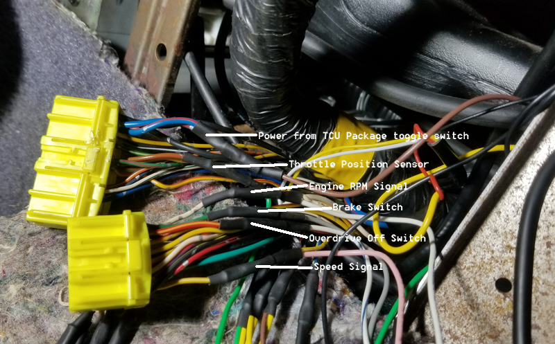
Install pictures on a 2G DSM with factory auto retaining TCU
Updating the firmware:
- The most recent SMART 100.1 firmware version is 007
- Please send an e-mail to
sales@forcedfour.com to inquire about updating your
firmware.
Downloading the PC software:
Confused? Contact us at
sales@forcedfour.com
|